


Functional principle Photoelectric proximity sensor
Functional principle detail Background suppression
Dimensions (W x H x D) 18 mm x 18 mm x 79.4 mm
Housing design (light emission) Cylindrical
Housing length 79.4 mm
Thread diameter (housing) M18 x 1
Optical axis Axial
Sensing range max. 25 mm ... 140 mm 1)
Sensing range 30 mm ... 130 mm
Focus Approx. 5°
Type of light Visible red light
Light source LED 2)
Light spot size (distance) Ø 12 mm (130 mm)
Angle of dispersion Approx. 5°
Wave length 660 nm
Adjustment Potentiometer, 270° (Sensing range)
Potentiometer, 270°
1) Object with 90% remission (based on standard white, DIN 5033).
2) Average service life: 100,000 h at TU = +25 °C.
Supply voltage UB 10 V DC ... 30 V DC 1)
Ripple ± 10 % 2)
Current consumption 30 mA 3)
Switching output PNP 4)
Switching mode Light/dark switching 4)
Switching mode selector Selectable via L/D control cable
Output current Imax. ≤ 100 mA
Response time ≤ 0.5 ms 5)
Switching frequency 1,000 Hz 6)
Connection type Male connector M12, 4-pin
Circuit protection
A 7)
B 8)
C 9)
D 10)
Protection class III
Weight 200 g
Housing material Metal, Nickel-plated brass
Optics material Plastic, PMMA
Enclosure rating IP67
Ambient operating temperature –25 °C ... +70 °C
Ambient temperature, storage –55 °C ... +80 °C
UL File No. NMFT2.E175606
1) Limit values.
2) May not fall below or exceed UV tolerances.
3) Without load.
4) Control wire open: dark switching D.ON.
5) Signal transit time with resistive load.
6) With light/dark ratio 1:1.
7) A = VS connections reverse-polarity protected.
8) B = inputs and output reverse-polarity protected.
9) C = interference suppression.
10) D = outputs overcurrent and short-circuit protected.
Leave Your Message
Products categories
-

1044369 DT50-P1113
-

1039018 AFS60B-S4AA008192
-

1072254 PGT-10-Pro
-

6011050 WT150-P460
-

6030710 WL100L-F2231
-

2029225 AD-ATM60-KA3PR
-

1067295 LUTM-UP81162P
-

1030015 ATM60-PAH13X13
-

6036841 WFL120-95B416
-

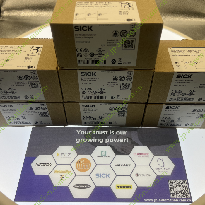
1052442 GTB6-P4212
-

1040885 IME08-04NPSZT0K
-

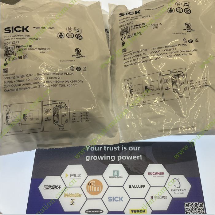
1062110 GL6-P4212
-

6026216 VT12T-2P430
-

1070853 RZT7-03ZRS-KWB
-

1082863 GTB6-P4241
-

6033209 WTB8-P2231
-

6052381 WL100-2N1429
-

6028449 WF120-95B410
-

6028440 WF50-60B410
-

6028441 WF80-60B410
-

6052384 WL100-2P1429
-

6063341 GLL170T-B434
-

1109504 DBS50E-SKEL02000
-

1055887 GL10-P4212
-

1036616 PGT-08-S
-

1218667 WTB26I-24161120A00
-

1222999 WTB4FP-21311120ZZZ
-

1029950 MM12-90APS-ZC0
-

6028431 WF30-40B410
-

6033188 WL8G-P2231
-

1064697 GTE10-P4211
-

1085344 RLY3-OSSD200
-

6020688 WL150-P420
-

6033182 WL8-P2231
-

1064243 GRTE18-N2442
-

1067295 LUTM-UP81162P
-

1065661 DT50-2B215252
-

1085344 RLY3-OSSD200
-

6020688 WL150-P420
-

6033182 WL8-P2231
-

1057652 DT35-B15251
-

1019229 WT34-B410
-

1222998 WTB4FP-22161120A00
-

2066614 BEF-1SHABPKU4
-

6013551 VL18-4P3240
-

1211516 C4C-EA09030A10000
-

1211498 C4C-SA09030A10000
-

1041032 IME30-15BPSZW2S
-

1062121 RE11-SK
-

1062121 RE11-SK
-

2095617 YF2A15-020UB5XLEAX
-

5321625 PL100
-

6013333 VTE18-4P4712
-

1066557 GRL18-P2432
-
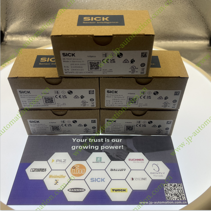
1105444 WTV4FE-22161120A00
-
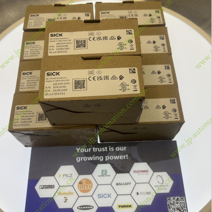
1041436 WL12-3P2431
-
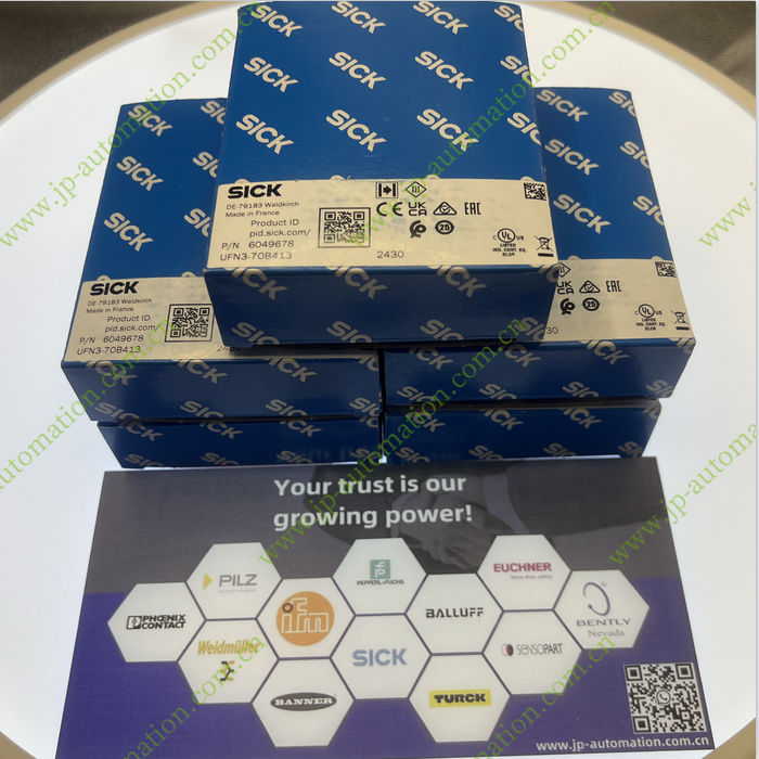
6049678 UFN3-70B413
-

1051784 GTE6-N1212
-

1018252 WL12L-2B530
-
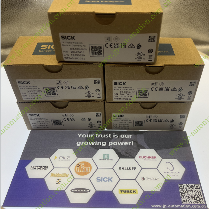
1042041 WTB4S-3P2261
-
1065857 GTB10-P4212
-
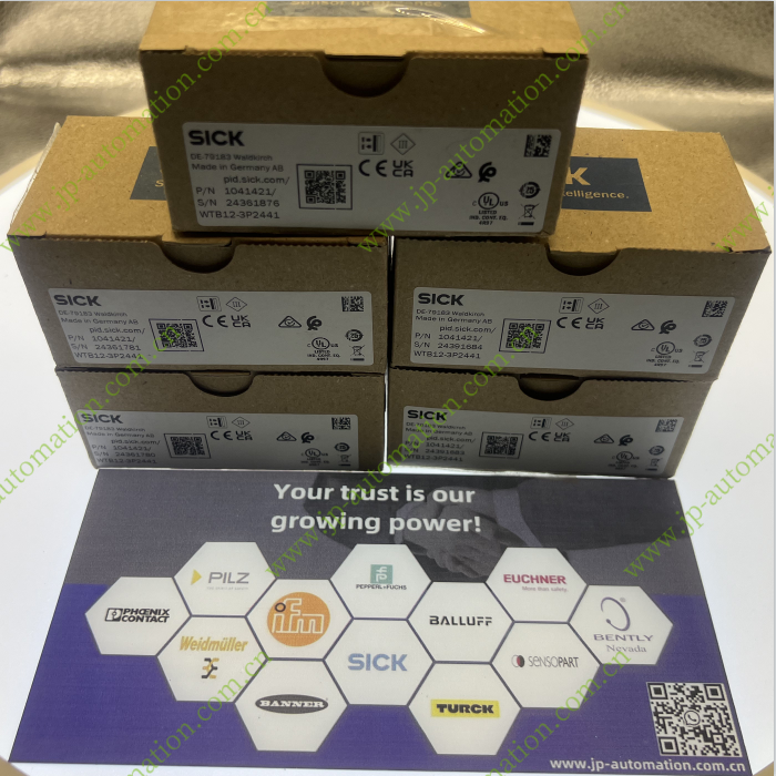
1041421 WTB12-3P2441
-
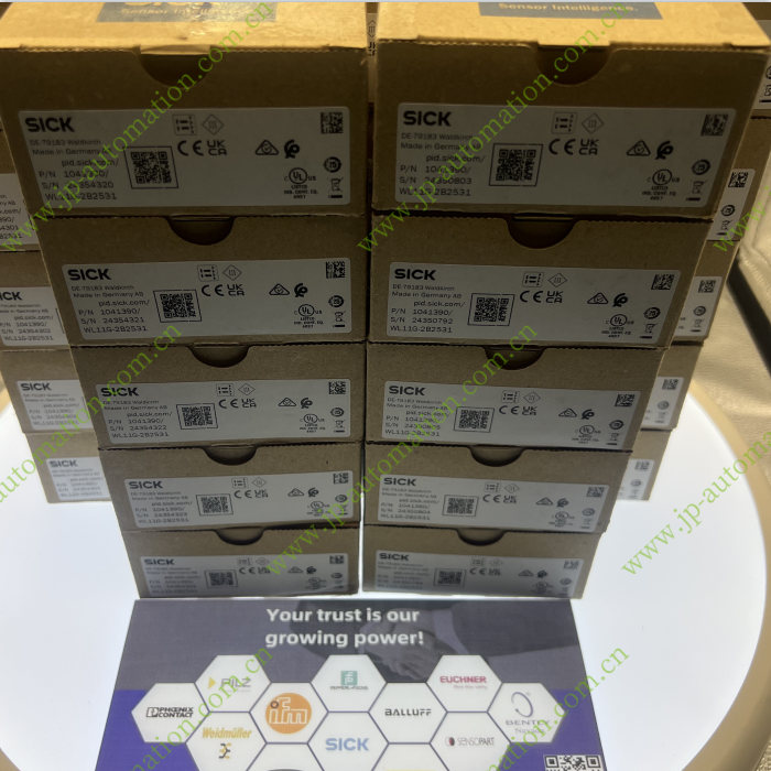
1041390 WL11G-2B2531
-
1059922 GL6-P1211
-

1082905 GTB6-N1241
-

6043919 WFS3-40P415
-

6063341 GLL170T-B434
-
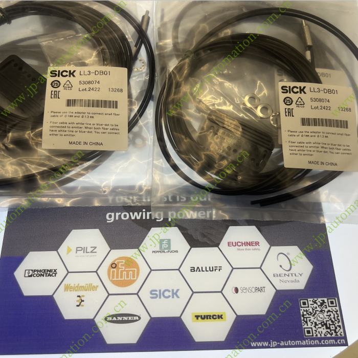
5308074 LL3-DB01
-
5308050 LL3-TB01
-
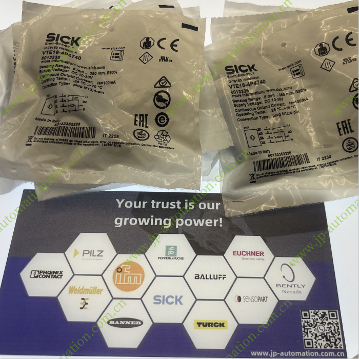
6013335 VTE18-4P4740
-
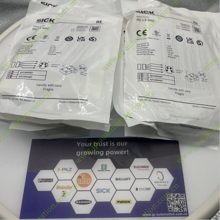
1059503 RE13-SAC
-
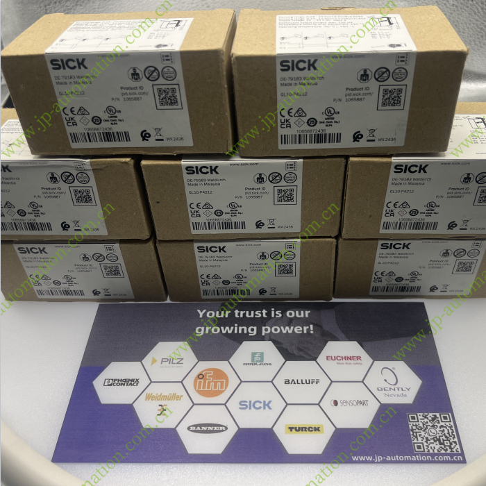
1065887 GL10-P4212
-
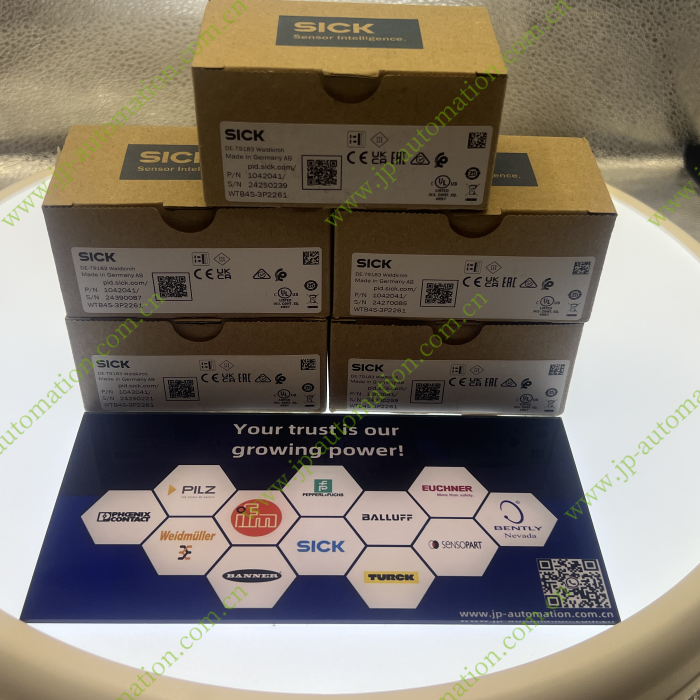
1042041 WTB4S-3P2261
-
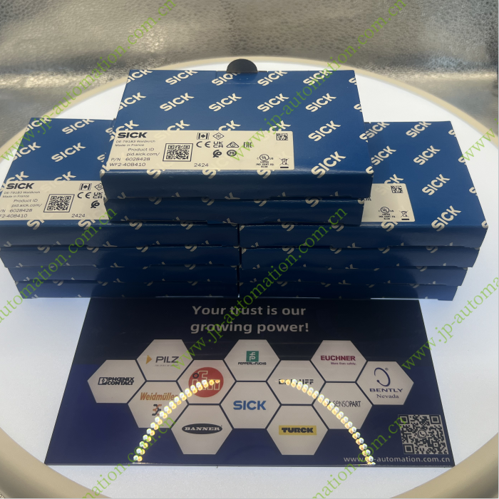
6028428 WF2-40B410
-
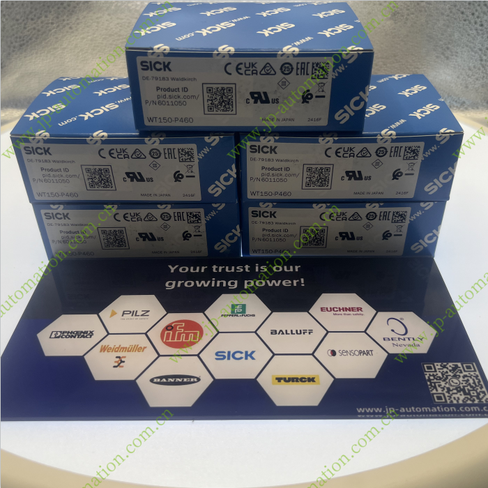
6011050 WT150-P460
-
1222999 WTB4FP-21311120ZZZ
-

1002314 PL30A
-
1060810 GL6G-P4212
-
1040878 IME08-02BNSZT0S
-
1221031 KTS-WS41141142ZZZZ
-

1078166 KTX-WS91142242ZZZZ
-
1078167 KTX-WS91141242ZZZZ
-

6049678 UFN3-70B413
-

5325944 LL3-TS22
-

1061397 GSE6-N4212
-

1060695 DBS50E-S5EK1024
-

1052443 GTB6-N4212
-

1078167 KTX-WS91141242ZZZZ
-

1040887 IME08-04NPSZW2K
-

2069592 BEF-WN-DX35
-

1060814 GL6-N1212
-

1065857 GTB10-P4212
-

1064706 GSE10-P4211
-

6052362 WL100-2P4439
-

6052386 WT100-2P4429
-

6052384 WL100-2P1429
-

6052373 WT100-2P3439
-

6052372 WT100-2P1439
-

6030704 WT100L-F2241
-

6052370 WT100-2N3439
-

6052371 WT100-2N4439
-

6030710 WL100L-F2231
-

6052374 WT100-2P4439
-

1040772 IME12-04BNSZC0S
-

1040748 IME12-04NPSZC0S
-

1040950 IME18-08NPSZ0S
-

1040782 IME12-08NPSZW2S
-

1040874 IME08-02BPOZ0S
-

1019244 WL34-V240
-

1078166 KTX-WS91142242ZZZZ
-

6052377 WT100-2N4419
-

1070847 RZT7-03ZRS-KR0
-

6063341 GLL170T-B434
-

1047581 DT50-P1114
-

2072580 DOS-2312-W01
-

1066552 GRTE18-P2462
-

1066549 GRTE18-P2442
-

1052444 GTB6-P1212
-

1066573 GRSE18-P2442
-

1040773 IME12-04BNSZW2K
-

2095838 YI214-100UB3XLEAX
-

UC4-13346 6054708
-

2029225 AD-ATM60-KA3PR
-

1109504 DBS50E-SKEL02000 DE-79183
-

1044442 WTB11-2P2461
-

1041380 WTF11-2P2431
-

1041404 WTF12-3P2431
-

1222998 WTB4FP-22161120A00
-

SICK
-

BANNER