


Power dissipation 1.3 W at 24 V , 270 Ω load
Input
Connection side control side
Connection terminals 5+, 6-
Test pulse length max. 2 ms from DO card
Signal level loop powered
1-signal: 19 ... 30 V DC
0-signal: 0 ... 5 V DC
bus powered
1-signal: 15 ... 30 V DC (current limited to 5 mA)
0-signal: 0 ... 5 V DC
Rated current Ir 0-signal: typ. 1.6 mA at 1.5 V DC; typ. 8 mA at 3 V DC (maximum leakage current DO
card)
1-signal: ≥ 36 mA (minimum load current DO card)
Inrush current < 200 mA , 10 ms loop powered
Output
Connection side field side
Connection terminals 1+, 2-
Internal resistor Ri 240 Ω
Current Ie typ. 45 mA
Voltage Ue typ. 12 V
Current limit Imax 50 mA
Open loop voltage Us typ. 24.6 V
Load nominal 0.05 ... 18 kΩ , valid range for line fault detection (LFD)
Output II fault signal
Connection terminals 7, 8 , non-intrinsically safe
Contact loading 30 V DC/ 0.5 A resistive load
Mechanical life 105 switching cycles
Energized/De-energized delay ≤ 20 ms / ≤ 20 ms
Line fault detection
Test current max. 350 µA , calculated by ILFD = 4.7 V / (15 kΩ + RLoad)
Galvanic isolation
Output/other circuits basic insulation according to IEC/EN 61010-1, rated insulation voltage 300 Veff
Output II/power supply basic insulation according to IEC/EN 61010-1, rated insulation voltage 32 Veff
Indicators/settings
Display elements LEDs
Control elements DIP switch
Configuration via DIP switches
Labeling space for labeling at the front
Directive conformity
Electromagnetic compatibility
Directive 2014/30/EU EN 61326-1:2013 (industrial locations)
Conformity
Electromagnetic compatibility NE 21:2012 , EN 61326-3-2:2008
For further information see system description.
Degree of protection IEC 60529:2013
Protection against electrical shock EN 61010-1:2010
Ambient conditions
Ambient temperature -20 ... 60 °C (-4 ... 140 °F)
Observe the temperature range limited by derating, see section derating.
Mechanical specifications
Degree of protection IP20
Connection screw terminals
Mass approx. 150 g
Dimensions 12.5 x 119 x 114 mm (0.5 x 4.7 x 4.5 inch) (W x H x D) , housing type A2
Mounting on 35 mm DIN mounting rail acc. to EN 60715:2001
Leave Your Message
Products categories
-

104095 UC6000-30GM-IUR2-V15
-

104093 UC2000-30GM-IUR2-V15
-

104094 UC4000-30GM-IUR2-V15
-

189784 KFD2-EB2.R4A.B
-

203355 KFD2-SR2-EX2.W
-

70159064 HIC2081
-

214240 KCD2-SOT-EX.LB
-

70104930 KCD2-SLD-EX1.1245
-
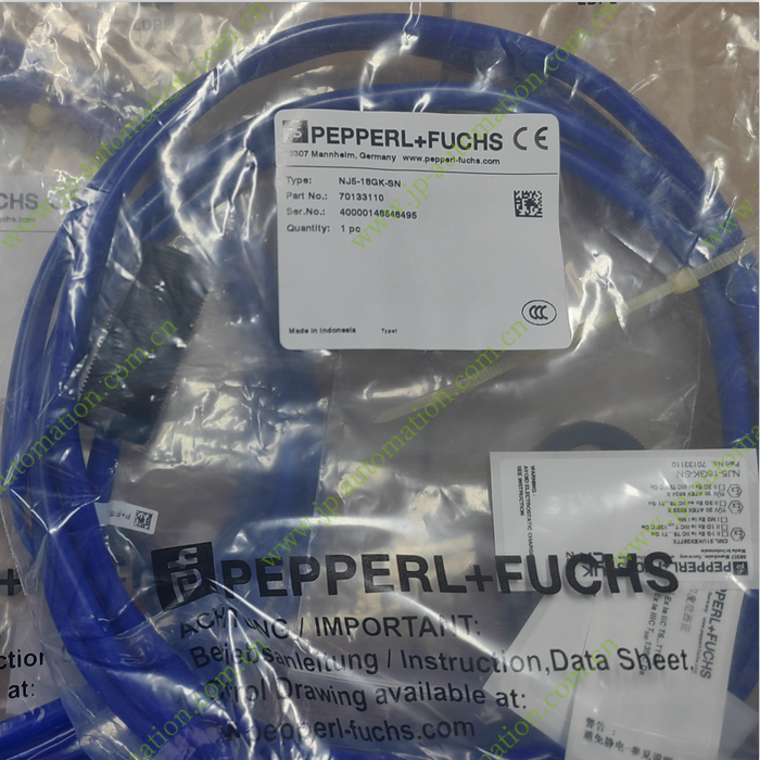
70133110 NJ5-18GK-SN
-

70134682 OBE10M-18GM60-SE5-V1-IR-1C
-

321423 HiC2025
-
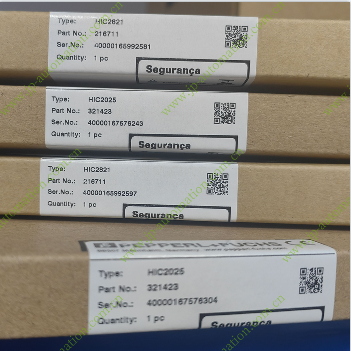
216711 HiC2821
-
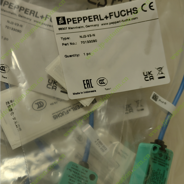
70133090 NJ2-V3-N
-
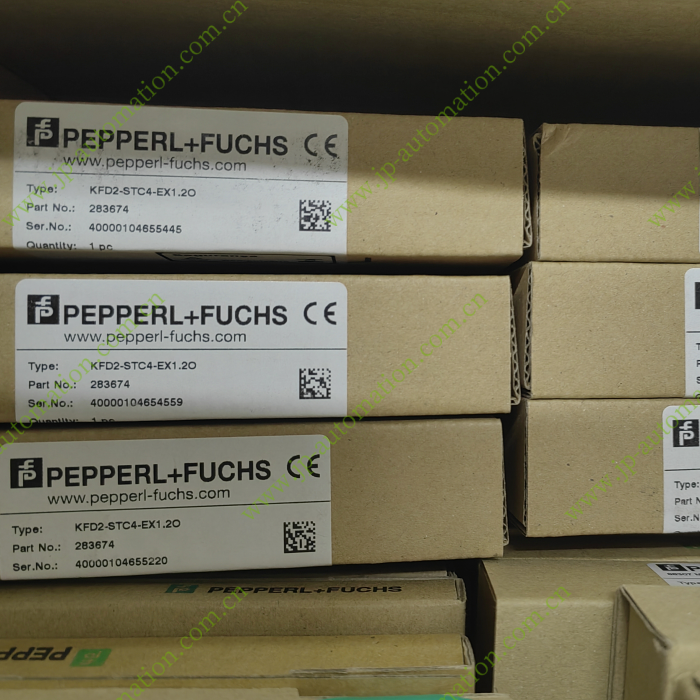
283674 KFD2-STC4-EX1.2O
-

70150440 KCD2-SCD-EX1
-

261533 K-HM26-2M-261533
-
261533 K-HM26-2M-261533
-
70107327 KFD2-VR4-EX1.26
-
203355 KFD2-SR2-EX2.W
-

Pepperl Fuchs