


General specifications
Signal type Analog output
Functional safety related parameters
Safety Integrity Level (SIL) SIL 2
Supply
Connection Power Rail or terminals 9+, 10-
Rated voltage Ur 19 ... 30 V DC
Ripple ≤ 10 %
Rated current Ir ≤ 30 mA
Power dissipation ≤ 600 mW
Power consumption ≤ 700 mW
Input
Connection side control side
Connection terminals 5-, 6+
Input signal 4 ... 20 mA limited to approx. 30 mA
Input voltage depending on switch configuration
open loop voltage of the control system < 23 V
open loop voltage of the control system < 27 V
Voltage drop depending on switch configuration
open loop voltage of the control system < 23 V: approx. 6 V at 20 mA
open loop voltage of the control system < 27 V: approx. 10 V at 20 mA
Input resistance > 100 kΩ, with field wiring open
Output
Connection side field side
Connection terminals 1+, 2-
Current 4 ... 20 mA
Load 0 ... 650 Ω
Voltage ≥ 13 V at 20 mA
Ripple 20 mV rms
Transfer characteristics
Accuracy 0.1 %
Deviation at 20 °C (68 °F), 0/4 ... 20 mA
≤ ± 0.1 % incl. non-linearity and hysteresis
Influence of ambient temperature < 2 µA/K (0 ... 60 °C (32 ... 140 °F)); < 4 µA/K (-20 ... 0 °C (-4 ... 32 °F))
Frequency range field side into the control side: bandwidth with 0.5 Vpp signal 0 ... 3 kHz (-3 dB)
control side into the field side: bandwidth with 0.5 Vpp signal 0 ... 3 kHz (-3 dB)
Rise time 10 to 90 % ≤ 100 ms
Galvanic isolation
Input/Output reinforced insulation acc. to EN 50178, rated insulation voltage 300 Veff
Input/power supply reinforced insulation acc. to EN 50178, rated insulation voltage 300 Veff
Output/power supply reinforced insulation acc. to EN 50178, rated insulation voltage 300 Veff
Indicators/settings
Display elements LED
Control elements DIP-switch
Configuration via DIP switches
Labeling space for labeling at the front
Directive conformity
Electromagnetic compatibility
Directive 2014/30/EU EN 61326-1:2013 (industrial locations)
Conformity
Electromagnetic compatibility NE 21
Degree of protection IEC 60529
Ambient conditions
Ambient temperature -20 ... 60 °C (-4 ... 140 °F)
Mechanical specifications
Degree of protection IP20
Connection screw terminals
Mass approx. 100 g
Dimensions 12.5 x 114 x 124 mm (0.5 x 4.5 x 4.9 inch) , housing type A2
Mounting on 35 mm DIN mounting rail acc. to EN 60715:2001
Data for application in connection
with hazardous areas
EU-type examination certificate CESI 06 ATEX 021
Marking ¬ II (1)G [Ex ia Ga] IIC , ¬ II (1)D [Ex ia Da] IIIC , ¬ I (M1) [Ex ia Ma] I
Output [Ex ia Ga] IIC, [Ex ia Da] IIIC, [Ex ia Ma]
Leave Your Message
Products categories
-

104095 UC6000-30GM-IUR2-V15
-

104093 UC2000-30GM-IUR2-V15
-

104094 UC4000-30GM-IUR2-V15
-

189784 KFD2-EB2.R4A.B
-

203355 KFD2-SR2-EX2.W
-

70159064 HIC2081
-

214240 KCD2-SOT-EX.LB
-

70104930 KCD2-SLD-EX1.1245
-

70104930 KCD2-SLD-EX1.1245
-
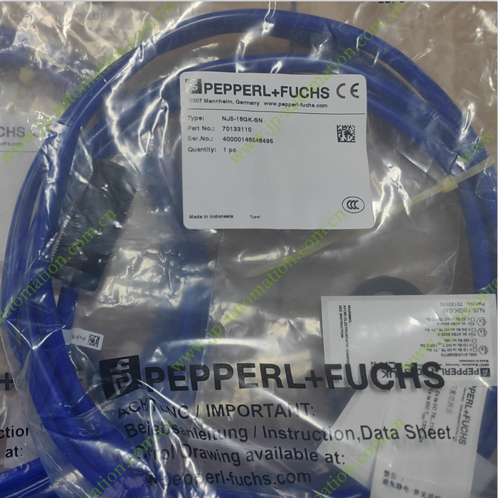
70133110 NJ5-18GK-SN
-

70134682 OBE10M-18GM60-SE5-V1-IR-1C
-

321423 HiC2025
-
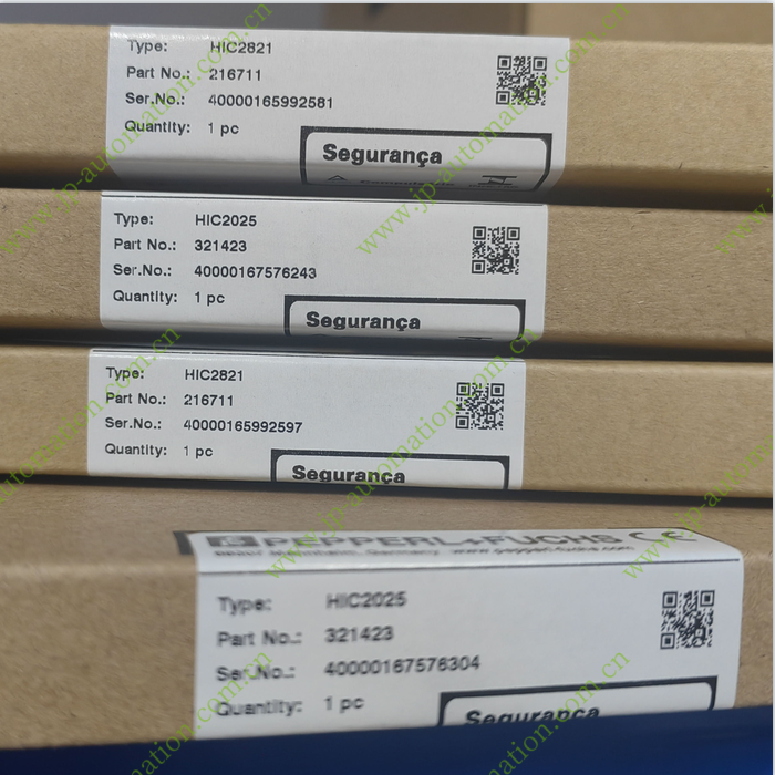
216711 HiC2821
-
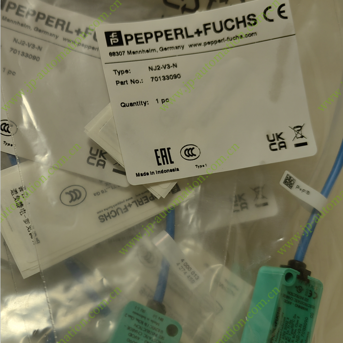
70133090 NJ2-V3-N
-
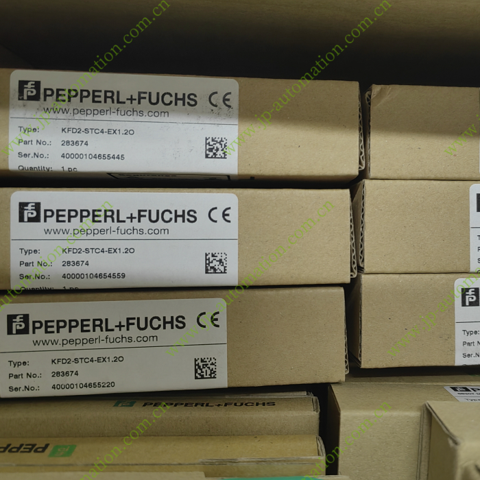
283674 KFD2-STC4-EX1.2O
-

261533 K-HM26-2M-261533
-
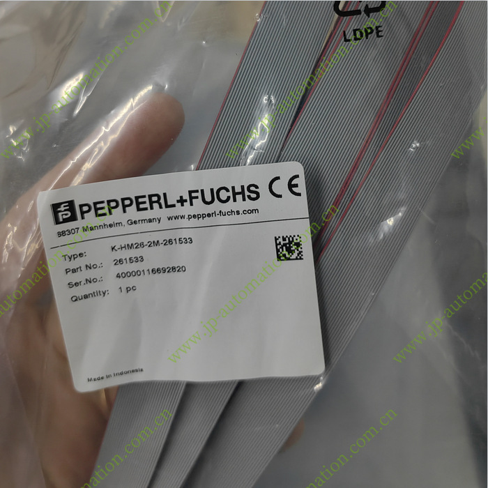
261533 K-HM26-2M-261533
-
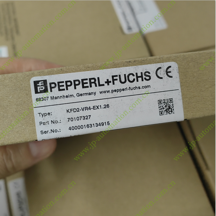
70107327 KFD2-VR4-EX1.26
-
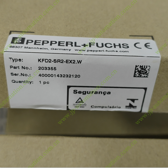
203355 KFD2-SR2-EX2.W
-

Pepperl Fuchs