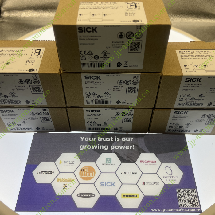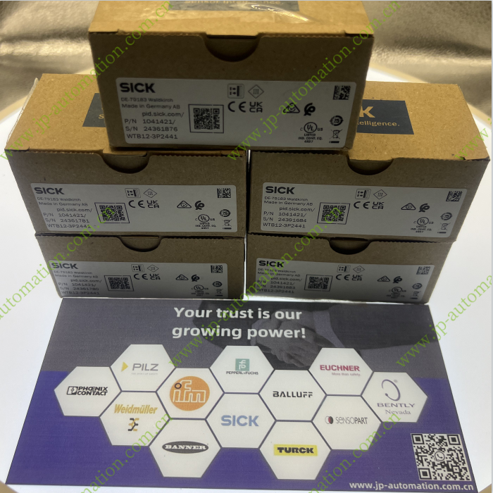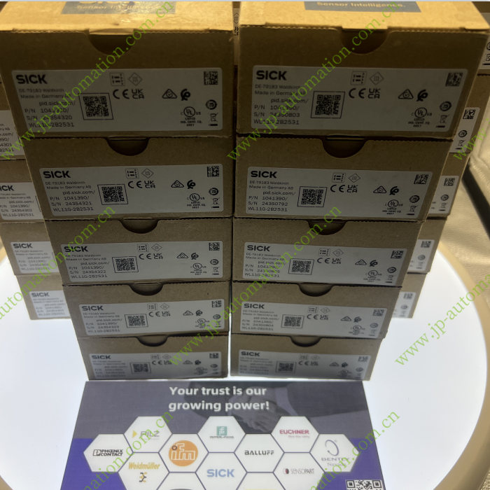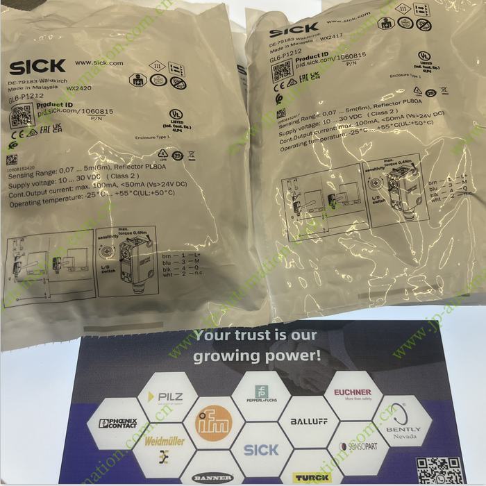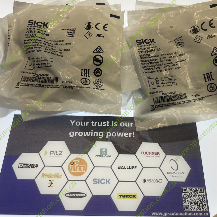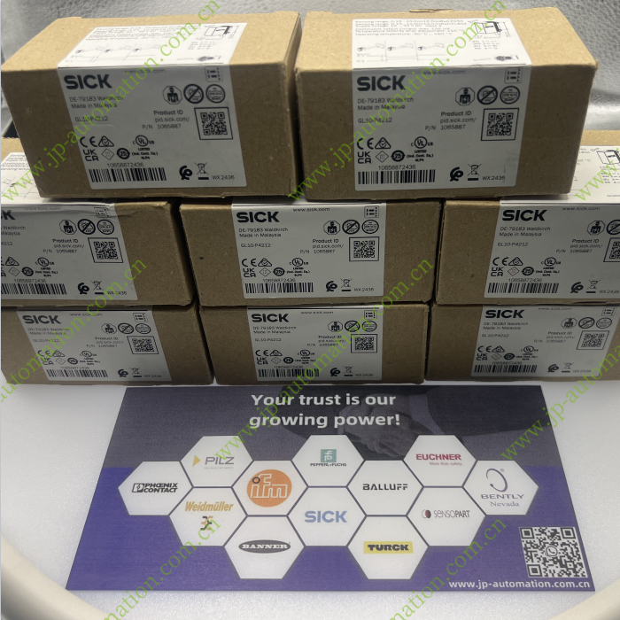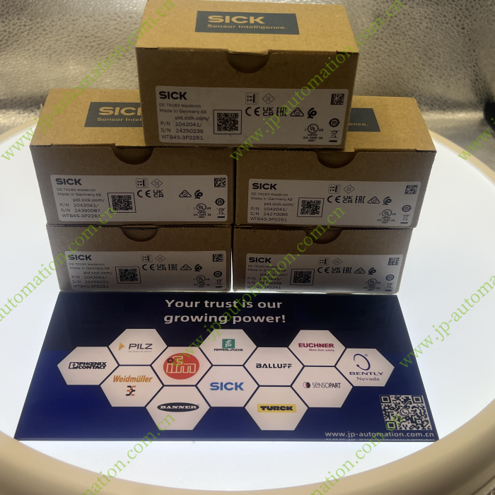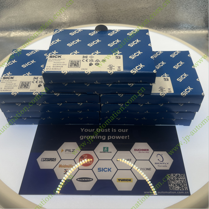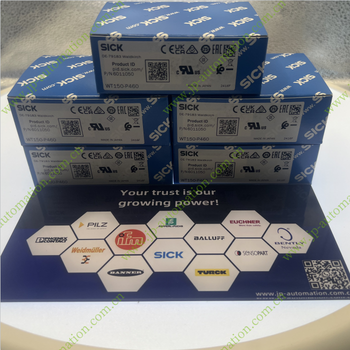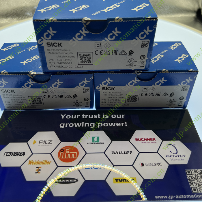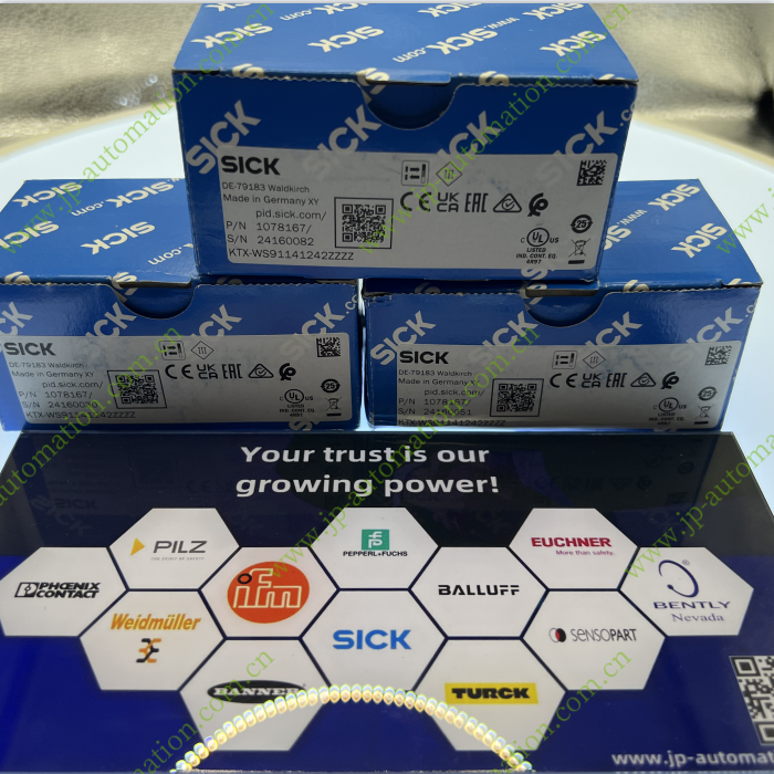

Functional principle Photoelectric proximity sensor
Functional principle detail Energetic
Dimensions (W x H x D) 12 mm x 12 mm x 65.5 mm
Housing design (light emission) Cylindrical
Housing length 65.5 mm
Thread diameter (housing) Round connector M12 x 1
Sensing range max. 0 mm ... 340 mm 1)
Sensing range 2 mm ... 300 mm
Focus Approx. 5.3°
Type of light Infrared light
Light source LED 2)
Light spot size (distance) Ø 28 mm (300 mm)
Angle of dispersion Approx. 5.3°
Wave length 880 nm
Adjustment Single teach-in button, Selectable via control input C (Sensing range, Sensing range) 3) 4)
1) Object with 90% remission (based on standard white, DIN 5033).
2) Average service life: 100,000 h at TU = +25 °C.
3) Manual, via teach-in button.
4) Electronically via control input C (0 V).
Supply voltage UB 10 V DC ... 30 V DC 1)
Ripple ± 10 % 2)
Current consumption 20 mA 3)
Switching output PNP
Switching mode Light/dark switching
Switching mode selector Selectable via control input C
Output current Imax. ≤ 100 mA 3)
Response time ≤ 1.25 ms 4)
Switching frequency 400 Hz 5)
Connection type Male connector M12, 4-pin
Circuit protection
A 6)
B 7)
C 8)
D 9)
Protection class III
Weight 18 g
Housing material Metal, Nickel-plated brass/PA
Optics material Plastic, PMMA
Enclosure rating IP67
Ambient operating temperature –25 °C ... +70 °C
Ambient temperature, storage –25 °C ... +70 °C
UL File No. E175606
1) Limit values.
2) May not exceed or fall below Uv tolerances.
3) Without load.
4) Signal transit time with resistive load.
5) With light/dark ratio 1:1.
6) A = VS connections reverse-polarity protected.
7) B = inputs and output reverse-polarity protected.
8) C = interference suppression.
9) D = outputs overcurrent and short-circuit protected.


